RelayTen
Last modified June 12, 2024 10:37pm
I designed a circuit board for I2C to control Ten Relays.
It also has a AM3220 Temperature Humidity Sensor and a Buzzer
(4000 Hz) and LED) and 5 TTL inputs via the P1 connector.
It should fix the WaveShare 4.3 and 7 inch ESP32 displays.
Those who have ordered a Board, they will be sent in for building soon this week
You should have them by June 20th I hope.
June 12th update. I will have boards by Friday if you believe the Post Office!
I will ship Friday or Saturday so you they should arrive on the 19th or 20th to you!


Packed with Fun Features
This board take a I2C input either by Qwiic or a 4 pin connector.
The MCP 23017 convert PortA abd 2 bits form PORTB to drive Ten Relays.
All NO NC and Common from each relay are brought out to screw terminals.
Any CPU with I2C, Raspberry PIs all flavors including Pi Zero's
and can control this Relay Ten Board. Also you can use ESP32's and
Arduino and other ST Micro CPUs too.

P1 Connector
- GPIOB 0 (in or out)
- VCC +5V DC
- GPIOB 1 (in or out)
- Ground
- GPIOB 2 (in or out)
- Ground
- GPIOB 3 (in or out)
- N.C.
- GPIOB 4 (in or out)
- N.C.
- GPIOB 5 Buzzer and LED (out)
- N.C.
- GPIOB 6 Relay B6 (can be used as input if relay is not stuffed)
- GPIOB 7 Relay B7 (can be used as input if relay is not stuffed)
- INT B (out)
- /Reset
I2C Plated Thru Holes
You can use the Plated Thru Hole for I2C connections
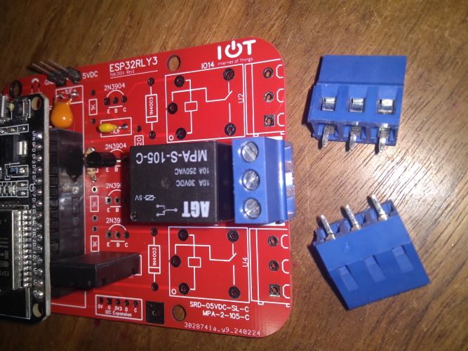
here is a top veiw of the Board.

Relays are under $1 each in quantities of ten
Buy Relays
I had great luck with
www.taydaelectronics.com
and also
www.pololu.com
3 Position Screw Terminal DG-128 Tayda SKU #A-3195
DG-128 Parts
Arduino
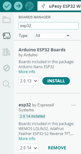
You can use the Arduino IDE for all ESP32 development as I did.
Install the ESP32 add on and for help check out
ESP32 Help
Mine looks like this
C++ Code Sketch
Address 0x20 PCB Jump LO+ADR
#include <Wire.h>

// MCP23017

const byte adr = 0x20; // MCP23017 address PCB Jump LO+ADR


// Casting is neeed for Wire.write() as it will
// write 1 2 or 4 bytes fr byte Int Long.


void setup()
{
  Wire.begin(); //creates a Wire object
  //Wire.setClock(400000); //Increase  I2C clock rate to 400 kHz or default 100K works too

  // set I/O pins to high
  Wire.beginTransmission(adr); //begins talking to the slave device
  Wire.write((byte)0x12); //selects the GPIO pins
  Wire.write((byte)0xff); // turns on pins 0 thru 7 on GPIOA
  byte r = Wire.endTransmission(); //stops talking to device

  Wire.beginTransmission(adr); //begins talking to the slave device
  Wire.write((byte)0x00); //selects the DIRA
  Wire.write((byte)0x00); // all outputs
  r = Wire.endTransmission(); //stops talking to device
}

void loop()
{
  Wire.beginTransmission(adr); //starts talking to slave device
  Wire.write((byte)0x12); //selects the GPIO pins
  Wire.write((byte)0xaa); // turns EVEN pins GPIOA
  byte r = Wire.endTransmission(); //ends communication with the device
  delay(50);


  Wire.beginTransmission(adr); //starts talking to slave device
  Wire.write((byte)0x12); //selects the GPIO pins
  Wire.write((byte)0x55); // turns on ODD pins of GPIOA
  r = Wire.endTransmission(); //ends communication with the device
  delay(50);
}
#END#